The 180-degree rotation (both clockwise and counterclockwise) is one of the simplest and most used transformations in geometry. Knowing how to apply this rotation inside and outside the Cartesian plane will open a wide range of applications in geometry, particularly when graphing more complex functions.
In this article, we want you to understand what makes this transformation unique, its fundamentals, and understand the two important methods we can use to rotate a figure 180 degrees (in either direction). We’ll be working with a reference point to extend our understanding to rotating figures on the Cartesian plane. By the end of our discussion, we want you to feel confident when asked to rotate different shapes and coordinates!
What Is a 180 Degree Rotation?
The 180-degree rotation is a transformation that returns a flipped version of the point or figures horizontally. When rotated with respect to a reference point (it’s normally the origin for rotations n the xy-plane), the angle formed between the pre-image and image is equal to 180 degrees. This means that we a figure is rotated in a 180-degree direction (clockwise or counterclockwise), the resulting image is the figure flipped over a horizontal line.

As a refresher, pre-image refers to the original figure and the image is the resulting figure after the Take a look at the two pairs of images shown above. After rotating the pre-images over a reference point, the resulting images are simply the pre-image being flipped over horizontally. Now, what happens when we flip a coordinate or a polygon on a Cartesian plane?
| Original Point (Pre-image) | Rotated Point (Image) |
| [katex]\begin{aligned}(x, y)\end{aligned}[/katex] | [katex]\begin{aligned}(-x, -y)\end{aligned}[/katex] |
When given a coordinate point, [katex](x, y)[/katex], when we rotate it a 180o degree rotation with respect to the origin, the resulting point will have coordinates that are the negative equivalents of the original point’s. It’s equivalent to flipping the point over the x-axis then the y-axis. To visualize this better, imagine rotating [katex]A = (4, 4)[/katex] in a 180-degree rotation with respect to the origin. The resulting point is [katex]A^{\prime}= (-4, -4)[/katex] as shown below.
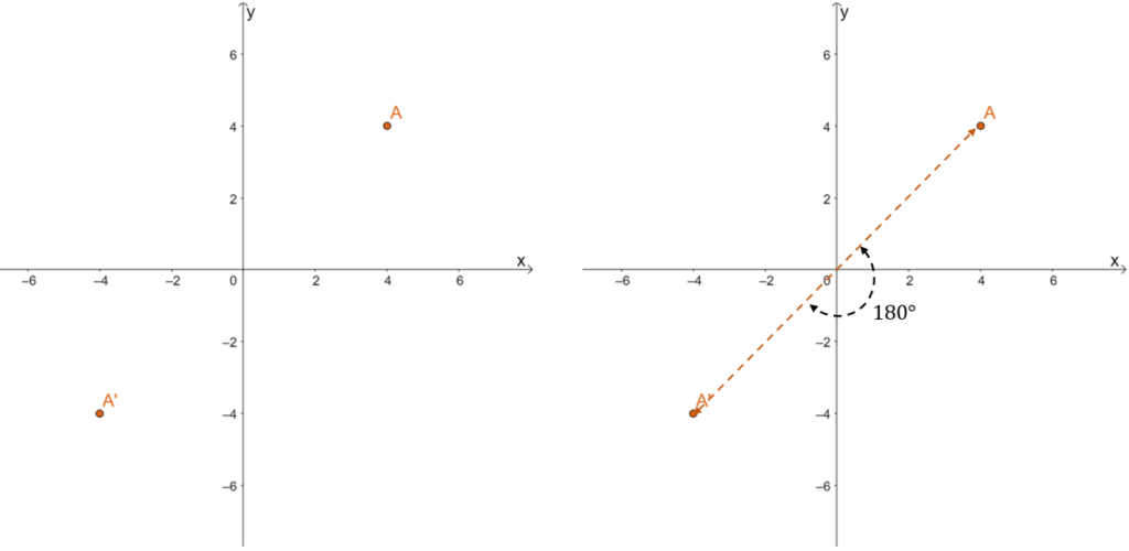
One way to locate the rotated point’s position is to connect the original point, [katex]A =(4,4)[/katex], with a line passing through the origin. The distance of A and A’ from the origin are equal, so the rotated point’s position is easy to spot. We’ve also learned that the rotated point’s coordinates will simply be the negative equivalents of the pre-image’s coordinates.
[katex] \begin{aligned}A \rightarrow A^{\prime}: (4, 4) \rightarrow(-4, -4)\end{aligned} [/katex]
Let’s now observe how 180 degree rotation affects figures like the rectangle shown below. The transformation shown below also confirms that the angles formed by [katex]A\rightarrow A^{\prime}[/katex], [katex]B\rightarrow B^{\prime}[/katex], [katex]C\rightarrow C^{\prime}[/katex], and [katex]D\rightarrow D^{\prime}[/katex] are all straight angles (meaning, they measure 180o). As expected, the resulting image is equivalent to flipping the rectangle, ABCD, over the x-axis followed by the y-axis.

Take a look at how the four vertices of ABCD are affected by the 180-degree rotation. We’re expecting the vertices’ coordinates to change to their negative equivalents and follow the transformation: [katex](x,y ) \rightarrow (-x, -y)[/katex].
| 180 Degree Rotation of Vertices | |
| [katex]\begin{aligned}A \rightarrow A^{\prime}\end{aligned}[/katex] | [katex] \begin{aligned}(2, 6) \rightarrow (-2, -6)\end{aligned} [/katex] |
| [katex] \begin{aligned}B \rightarrow B^{\prime}\end{aligned} [/katex] | [katex] \begin{aligned}(2, 2) \rightarrow (-2, -2)\end{aligned}[/katex] |
| [katex] \begin{aligned}C \rightarrow C^{\prime}\end{aligned} [/katex] | [katex] \begin{aligned}(7, 2) \rightarrow (-7, -2)\end{aligned} [/katex] |
| [katex] \begin{aligned}D \rightarrow D^{\prime}\end{aligned}[/katex] | [katex] \begin{aligned}(7, 6) \rightarrow (-7, -6)\end{aligned}[/katex] |
This confirms that when finding the coordinate of the resulting image, simply multiply the pre-image’s coordinates by -1 each. Before moving on to the next section, test your knowledge first by working on the problem that follows.
Problem 1
The point, A, is rotated 180o degrees to project the resulting point, A’. The same goes for the three other pairs of points.

Which of the pairs of points do not reflect the correct result after the point is rotated at 180 degrees?
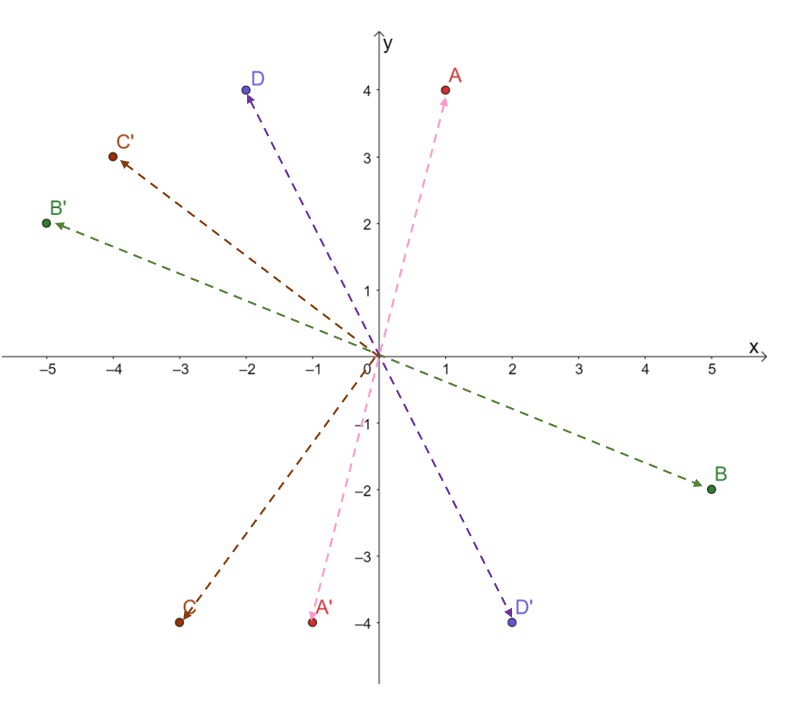
Observe the angle formed between the segments connecting the origin with the pre-image and image.
- The three projections, [katex]A \rightarrow A^{\prime}[/katex], [katex]B \rightarrow B^{\prime}[/katex], and [katex]D\rightarrow D^{\prime}[/katex], all form the straight angles.
- Looking at the remaining point, [katex]C\rightarrow C^{\prime}[/katex], the two rays meet and form a right angle (angle measuring 90o).
From this, it is safe to conclude that C is not rotated properly in a 180o angle with respect to the origin. But there is another way to double-check this- by observing how each of the points’ coordinates change after being rotated at 180o.
| [katex] \begin{aligned}A \rightarrow A^{\prime}\end{aligned} [/katex] | [katex] \begin{aligned}(1, 4) \rightarrow (-1, -4)\end{aligned} [/katex] |
| [katex] \begin{aligned}B \rightarrow B^{\prime}\end{aligned} [/katex] | [katex]\begin{aligned}(5, -2) \rightarrow (-5, 2)\end{aligned}[/katex] |
| [katex] \begin{aligned}C \rightarrow C^{\prime}\end{aligned} [/katex] | [katex]\begin{aligned}(-3, -4) \rightarrow (-4, 3)\end{aligned}[/katex] |
| [katex] \begin{aligned}D \rightarrow D^{\prime}\end{aligned} [/katex] | [katex]\begin{aligned}(2, -4) \rightarrow (-2, 4)\end{aligned}[/katex] |
The three pairs of points other than [katex]C\rightarrow C^{\prime}[/katex], exhibit the expected behavior of points being rotated at 180 degrees.
Now that we’ve established the fundamentals of a 180-degree rotation, it’s time to break down the steps needed to rotate figures.
How To Transform a Figure in a 180 Degree Rotation?
There are two ways to transform a point or a figure and rotate it 180 degrees with respect to a point or an origin. Use the reference point and construct two rays equidistant from it or apply the rules for coordinates when the figure is graphed on a xy-plane.
The first method is helpful when we’re working with a figure outside the Cartesian plane. When rotating an object at a 180-degree angle with respect to a reference point, flip the object horizontally then vertically. The reference point must still be equidistant from the pre-image and image’ positions.
Problem 2
Apply this method to rotate the pre-image (pentagon) shown below. Describe the resulting image’s shape.

When rotating the thunder symbol at 180 degrees, construct a line segment connecting the pre-image of the hexagon and the reference point.

The reason we’re doing this is that we want to form a straight angle to guide us in finding the resulting image after the 180-degree rotation. Now, connect this with a segment sharing the same length to mark the position of the resulting image. We expect the image to be identical to the pre-image, but this time, it’s flipped over horizontally.

This shows that the resulting image of the hexagon after we’ve performed 180-degree rotation is equivalent to the pre-image being flipped over horizontally then vertically. The shape and size of the figure remain the same – this means that this transformation is also an example of isometry (transformations that do not affect shape and size).
Now, what if we’re rotating on a Cartesian plane? This process is simpler if we’re given the vertices of the figure. Apply what we’ve learned about the effects of a 180-degree rotation on the coordinates of the figures. By rotating the key points, we’ll have an idea of how the rotation affects the entire graph. Connect the rotated vertices to construct the resulting image.
Problem 3
Let’s try out this method to rotate a line passing through the points, A = (4, 5) and B = (-6, -5), by 180o degrees.
We only need two points to graph a line, so to find the resulting line after the 180-degree rotation, we only need to focus on the two given points. As we have mentioned, multiply the pre-image’s coordinates by -1 to find the resulting coordinates of the image after the 180-degree rotation.
[katex]\begin{aligned}A = (4, 5) &\rightarrow A^{\prime}= (-4, -5)\\ B = (-6, -5) &\rightarrow A^{\prime}= (6, 5)\end{aligned}[/katex]

Now that we have the coordinates for the rotated points, simply connect the two to form the line segment. Check out the two lines shown above – highlighting the effect of a 180-degree rotation on AB.
Problem 4
Use a similar process to rotate the triangle, [katex]\Delta ABC[/katex], as shown below. Extend the xy-plane and construct the resulting image after a 180-degree transformation.
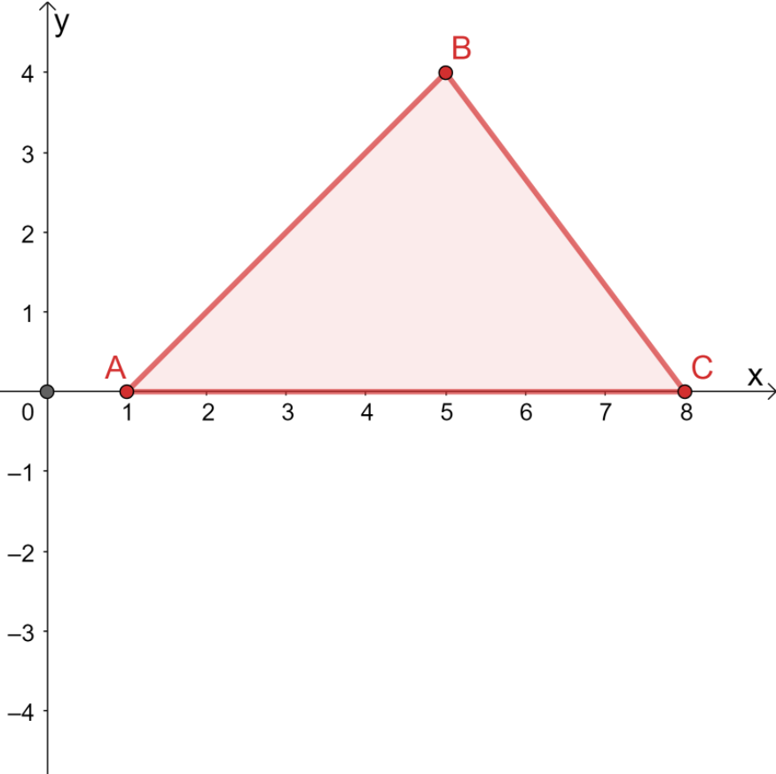
When rotating a point or a figure on the xy-plane, take note of the important vertices. For the case of [katex]\Delta ABC[/katex], we have the following coordinates of its vertices:
[katex]\begin{aligned}A &= (1, 0)\\B&= (5, 4)\\C &= (8, 0)\end{aligned}[/katex]
When applying a 180 degree rotation on a point, simply multiply its coordinates by -1. Apply the same process for all three vertices of the triangle. These rotated points will be the vertices of the resulting image.
| [katex] \begin{aligned}\Delta ABC \rightarrow \Delta A^{\prime}\Delta B^{\prime}C^{\prime}\end{aligned} [/katex] | |
| [katex] \begin{aligned}A \rightarrow A^{\prime}\end{aligned} [/katex] | [katex] \begin{aligned}(1, 0) \rightarrow (-1, 0)\end{aligned} [/katex] |
| [katex] \begin{aligned}B \rightarrow B^{\prime}\end{aligned} [/katex] | [katex] \begin{aligned}(5, 4) \rightarrow (-5, -4)\end{aligned} [/katex] |
| [katex] \begin{aligned}C \rightarrow C^{\prime}\end{aligned} [/katex] | [katex] \begin{aligned}(8, 0) \rightarrow (-8, 0)\end{aligned} [/katex] |
Now that we have the vertices for the rotated triangle, connect all three to form the rotated triangle, [katex]\Delta A^{\prime}B^{\prime}C^{\prime}[/katex].

The image of the triangle will now have vertices at the following points: (-1, 0), (-5, -4), and (-8, 0). Looking at the two triangles, we can also confirm that the resulting triangle is simply equivalent to flipping the pre-image over the x-axis then over the y-axis.